Where K is the radius of gyration of the ship. Lashing Calculation for Ship LASHCON Pad-Eye Design Spreadsheet Calculator.

Ultimate Load Capacities Of Mooring Bollards And Hull Foundation Structures Sciencedirect
Towing Bridle Design Spreadsheet Calculator.

. One Bollard Two Bollards. Design of Fixed Structures. Bollards The Anvil Series of mooring bollards was designed utilizing Finite Element Analysis and confirmed with physical testing and engineering calculations.
Some of the most commonly used bollard designs today are the Single Bitt Double Bitt T-head Horn or some known as Staghorn Kidney-shaped and some variable double head bollard designs. Steel bollards which provide high impact resistance but require regular painting to prevent corrosion. We do however recommend mooring loads to be calculated at all times.
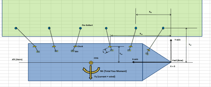
The calculation shall be based on the total mass of the system and the stiffness of the mooring lines in surge. Mooring lines are 15 longer - from bitts to bollards - then the distance between bollards and chocks. The formula for calculating the coefficient is given as follows BSI 2014.
Usually the anchor material would be A449 although I just quoted a job. Tie-Down Calculation for Barge. S effort force in the rope N lb F load force N lbf e 2718.
Changes to shore mooring points and bollard strength in Section 1461 to 1464. The calculation process includes calculate the mooring loads chain size chain length sinker size swinging circle radius and the reserve buoyancy of the buoy. The shape of Trelleborg bollards has been refined with finite element techniques to optimize the geometry and anchor layout.
It is not intended to be a design tool or provide engineered. Certain designs have double bollards for ropes to be cross-fastened. Without the anchor bolt stud the bollard would simply slide right the dock.
Check that safety factors are always greater than 10. The anchors are embedded in the concrete to match the bolt pattern on the base of the bollard. 56 Fender System Design References 6.
The effort force in a rope around a bollard can be calculated as. DISPLACEMENT BOLLARD RATING Approx Up to 2000 T 10 T 2000-10000 T 30 T 10000-20000 T 60 T 20000-50000 T 80 T 50000-100000 T 100 T 100000-200000 T 150 T Over 200000 T 200 T. The surge motion of the moored vessel is estimated by analyzing the vessel motion as a harmonically forced linear single degree of freedom spring mass system.
fittings including hull foundation structures. K 019Cb 011 L L is the length of the hull between perpendiculars m. Determine the natural period of the vessel and mooring system.
Additionally PT Kemenangan has the capability to do an actual pull test which can be done to in our workshop or at the installed sites at docks or jetties. Standard design and standard SWLs of mooring fittings however it is necessary to re-assess the ultimate load capacities of mooring. Types of Bollards.
To make the computation assume that. The formula for calculating the coefficient is given as follows BSI 2014. S F e- μ αrad 1 where.
Sections 1048 1264 and 1465 to 1466 have been moved from Guidelines for Load-outs. Mooring bollard design calculations It is less complicated than quick to build exceptional nail art for short nails. Our calculation can be done in manual as well as with stress simulation software.
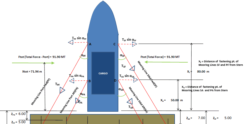
Design wise mooring bollard should have a thicker diameter at the top head tip of the structure to prevent mooring lines to escape accidentally. Bollard capacity tonnes 2000 10 200010000 30 1000020000 60 2000050000 80 50000100000 100 100000150000 150 150000200000 200 200000 300 According to common codes bollards should be spaced at intervals of 15 of the shortest ship design used on the berth. The mooring lines are horizontal.
A general guidelines to mooring loads can be followed from the below table. Mooring Loads and Design Principles 61 Mooring System Principles 62 Mooring Lines Hardware and Equipment 63 Wind Forces 64 Current Forces 65 Standoff Forces and Passing Vessel Effects 66 Wave Loads and Vessel Motions 67 Analytical Treatment and Modeling References 7. Such an arrangement would provide a tighter connection.
Even at full working load Trelleborg bollards remain highly stable and provide a safe and secure mooring. Cargo Force. It incorporates preferences found in the North American Market.
For wind force the formula is F wind 12 x C wind x ρ wind x V wind2 x A wind where C wind is the coefficient of wind force ρ wind is the density of air V wind is the wind speed and A wind is the total area of ship and cargo which is exposed to the wind from head or beam direction the above-water area. Garo213 MarineOcean OP 6 Aug 07 1424. Cb is the block coefficient Cb displacement kg L m x beam m x draft m x density of water kgm3.
Ship sizes Angles and spacing Approx. Atook you are correct. All you should do should be to introduce some glitter in.
Ship Load Trim and Stability Calculator. If the calculated swinging radius does not meet navigational requirements then the mooring design can be recal-. Cb is the block coefficient Cb displacement kg L m x.
μ friction coefficient approximately 03 - 05 is common for a rope around a steel or cast iron bollard αrad 2 π αdegrees 360 angle where the rope is in contact. Tow Line Static Catenary Calculation. It is important to provide a solid anchor point for mooring ropes.
Where K is the radius of gyration of the ship. All you should do should be to introduce some glitter in. K 019Cb 011 L L is the length of the hull between perpendiculars m.
C3 -10. The Anvil Series is a strong design developed with expert analysis and is proven with physical testing. CALPIPE SECURITY BOLLARDS.
PT Kemenangan has the team and expertise to calculate mooring load of marine bollard based on the working parameters in industry standards. Also known as US Style Pillar Bollards it is perfect for large tidal range berths. Allowable Bollard Deflection Distance.
67 Mooring system 15 7 DESIGN ENVIRONMENTAL CONDITIONS 16 71 General 16 72 Unrestricted operations 16 73 Weather-restricted operations 16. Ship Longitudinal Strength Limit Calculator. Smit Bracket Design Spreadsheet.
Further details on this exact process will be shared on next articles.
Vessel With Stern On Quay A Simplified Method For Mooring Design Thenavalarch

Bollard Strength Check Spreadsheet Www Thenavalarch Com Boat Design Net
2
Designing The Berth Mooring Of Your Vessel With This Simple Yet Effective Method Thenavalarch

Pdf Ultimate Load Capacities Of Mooring Bollards And Hull Foundation Structures

Bollard Requirement Pdf Rope Strength Of Materials
Pdf Ultimate Load Capacities Of Mooring Bollards And Hull Foundation Structures
2
0 comments
Post a Comment